Author: Nicholas Russo
Pardon the clickbait blog title, but I’m being serious. One of the most annoying things to troubleshoot in networking is a Maximum Transmission Unit (MTU) problem. For those unfamiliar, the MTU is the upper bound on the size of a datagram that may egress out of a given interface. Different MTUs exist at different layers of the OSI model too: Ethernet MTU, MPLS MTU, IPv4/v6 MTU, and more. Even Transmission Control Protocol (TCP) has a concept of Maximum Segment Size (MSS), which operates similarly. The difficulty in determining these upper bounds becomes complex as more encapsulation is added: tunnel headers, VLAN tags, MPLS labels … the list goes on.
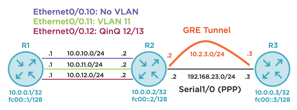
Consider the topology below. There are three routers in a line topology using a variety of link types. R1 has three logical connections to R2: native Ethernet, single 802.1Q tag, and double 802.1Q tag (QinQ). Each of these links is also running Label Distribution Protocol (LDP) for MPLS label exchange. R2 has a single Point-to-Point Protocol (PPP) connection to R3 that serves as an underlay for a Generic Routing Encapsulation (GRE) tunnel between the same two devices. OSPFv3 is running alongside LDP on all links except the R2-R3 PPP underlay to exchange IPv4 and IPv6 routes. IPv6 link-local addressing follows the fe80::X format where X is the router ID; this is not depicted for brevity.
Now, the moment you’ve all been waiting for. The base command is “show adjacency” which displays the Cisco Express Forwarding (CEF) adjacency table. I’m less interested in discussing internal router architecture/data structures and more interesting in explaining how this command will benefit real-life network operators. Consider R1’s “show adjacency” output below.
R1#show adjacency
Protocol Interface                 Address
IP       Ethernet0/0.10            10.0.10.2(16)
TAG      Ethernet0/0.10            10.0.10.2(5)
IPV6     Ethernet0/0.10            FE80::2(9)
IP       Ethernet0/0.11            10.0.11.2(16)
TAG      Ethernet0/0.11            10.0.11.2(5)
IPV6     Ethernet0/0.11            FE80::2(9)
IP       Ethernet0/0.12            10.0.12.2(16)
TAG      Ethernet0/0.12            10.0.12.2(5)
IPV6     Ethernet0/0.12            FE80::2(9)
There are nine entries: three for IPv4, three for IPv6, and three for “TAG”, which means MPLS. As shown in the diagram earlier, VLAN 10 is native Ethernet, VLAN 11 has one 802.1Q tag, and VLAN 12 has two 802.1Q tags. The address column shows the relevant next-hop information based on the unicast routing design. So far, this isn’t very interesting. Let’s dig deeper into the IPv4 entry on Ethernet0/0.10, the untagged interface. You can filter based on the link type (IPv4, IPv6, or MPLS), interface ID, and a few other fields.
R1#show adjacency Ethernet0/0.10 link ipv4 detail
Protocol Interface                 Address
IP       Ethernet0/0.10            10.0.10.2(16)
                                   0 packets, 0 bytes
                                   epoch 0
                                   sourced in sev-epoch 0
                                   Encap length 14
                                   AABBCC000200AABBCC0001000800
                                   ARP
Using the “detail” keyword, the router provides additional details. To keep this blog focused on MTU troubleshooting, we’ll limit our examination to the encapsulation details. According to the output, the encapsulation length is 14 bytes, followed by a hexadecimal string of 28 characters. It just so happens that a standard Ethernet header is 14 bytes long, ignoring layer-1 details like the preamble and Cyclic Redundancy Check (CRC). The first 6 bytes represent the destination MAC address (the MAC bound to 10.0.10.2), the next 6 bytes represent the source MAC address (R1’s MAC on Ethernet0/0), and the last 2 bytes represent the Ethertype of 0x0800. This code indicates that the Ethernet frame would carry an IPv4 payload. You’ll have to take my word for it on the 0x0800 Ethertype (I promise I’m not lying), but we can verify the MAC addresses by checking the IPv4 Address Resolution Protocol (ARP) cache.
R1#show ip arp Ethernet0/0.10
Protocol  Address     Age (min)  Hardware Addr   Type   Interface
Internet  10.0.10.1          -   aabb.cc00.0100  ARPA   Ethernet0/0.10
Internet  10.0.10.2         13   aabb.cc00.0200  ARPA   Ethernet0/0.10
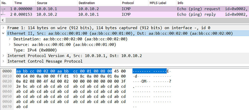
You can see that R2’s MAC is the first 6 bytes and R1’s MAC is the second 6 bytes, which is correct. For the ultra-skeptical, here’s a packet capture to prove that the router is indeed telling the truth. I’ve highlighted the 14-byte Ethernet encapsulation string that exactly matches the “show adjacency” output discussed earlier.
Let’s try another example, this time targeting the IPv6 adjacency over VLAN 11. This link uses one 802.1Q tag.
R1#show adjacency Ethernet0/0.11 link ipv6 detail
Protocol Interface                 Address
IPV6     Ethernet0/0.11            FE80::2(9)
                                   0 packets, 0 bytes
                                   epoch 0
                                   sourced in sev-epoch 0
                                   Encap length 18
                                   AABBCC000200AABBCC0001008100000B
                                   86DD
                                   IPv6 ND
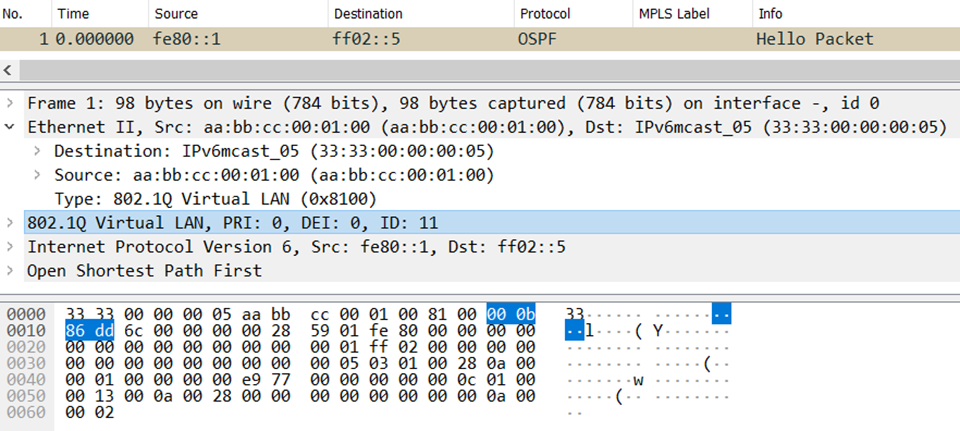
What differences can you see? First, the encapsulation length is now 18 bytes. Single-tagged VLANs require the standard 14-byte Ethernet header just described, plus the 4-byte 802.1Q encapsulation. The first 12 bytes are the same (source and destination MAC) and next comes 0x8100. This is the Ethertype for 802.1Q, signaling that the next 4 bytes will be a VLAN tag. Bits 5 through 16 (12 bits in total) signal the VLAN value, which is 0x00B (decimal 11). The last 2 bytes of the 802.1Q header include the Ethertype of the next header in the encapsulation stack. A value of 0x86DD represents the Ethertype of IPv6, indicating that these Ethernet frames contain IPv6 payloads. In the picture below, I’ve highlighted the 4-byte VLAN tag. Just before it, you can see the 14-byte Ethernet header ending with 0x8100 to signal the presence of 802.1Q encapsulation.
Let’s try a more complex example. We’ll ask R1 about its MPLS adjacency on the VLAN 12 interface, which uses QinQ tunneling.
R1#show adjacency Ethernet0/0.12 link mpls detail
Protocol Interface                 Address
TAG      Ethernet0/0.12            10.0.12.2(5)
                                   0 packets, 0 bytes
                                   epoch 0
                                   sourced in sev-epoch 0
                                   Encap length 22
                                   AABBCC000200AABBCC0001008100000C
                                   8100000D8847
                                   ARP
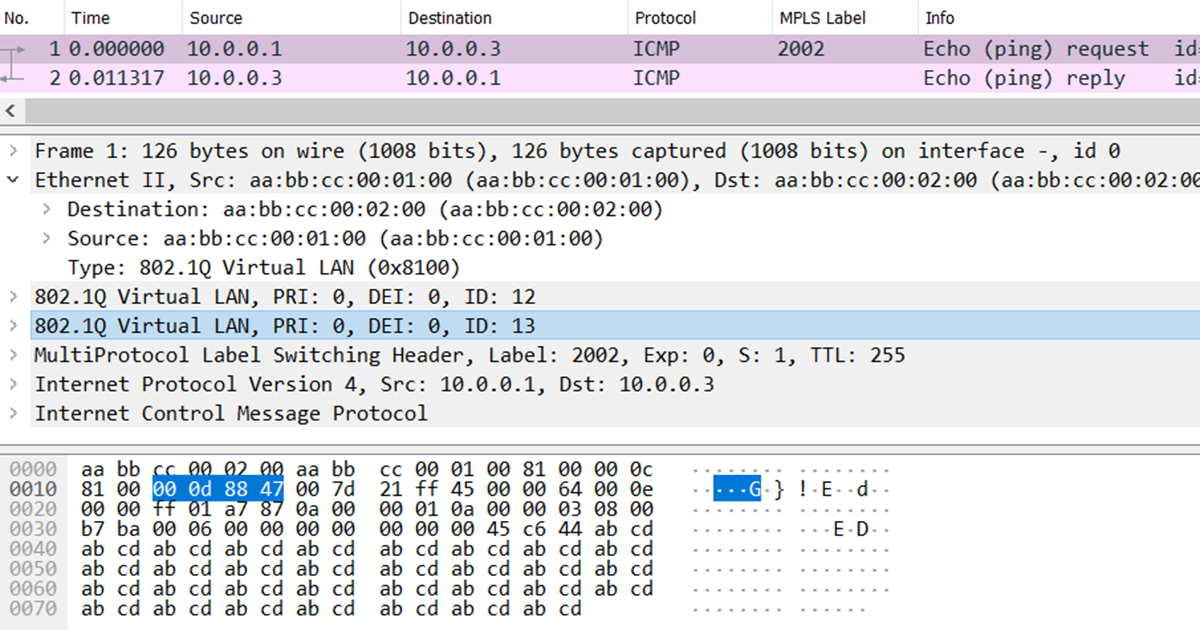
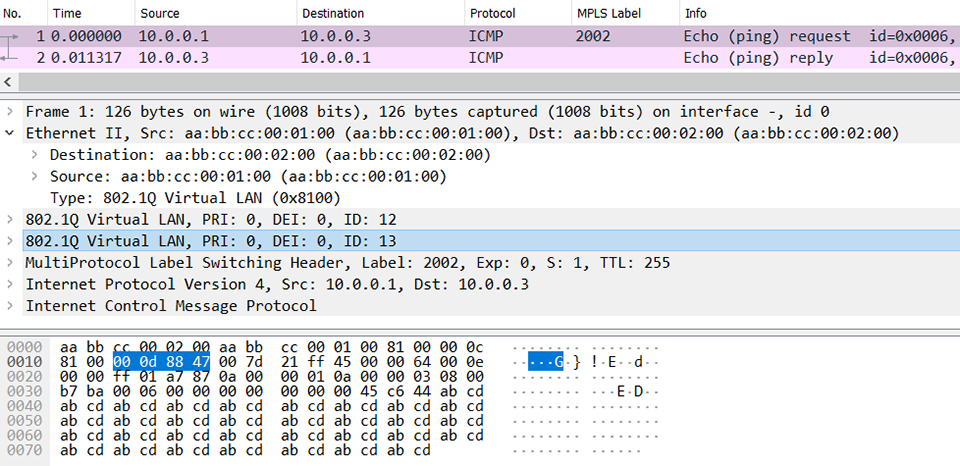
I ask again, what’s changed? The encapsulation length has increased by 4 bytes again and is now 22 bytes. This is to account for the additional VLAN tag. The first 12 bytes remain the same, followed by the first Ethertype of 0x8100 for 802.1Q. The VLAN ID of the outer tag is 0x00C (decimal 12) and the VLAN ID of the inner tag is 0x00D (decimal 13). Like MPLS labels, VLAN tags can be stacked in much the same way but be sure to account for the 4-byte length of each one. The last 2 bytes of the inner VLAN header is 0x8847. This is the Ethertype for MPLS unicast, correctly indicating the payload. Keep in mind that “show adjacency” will not reveal the MPLS label stack because it varies per destination, but I’ll show you how to discover it later. Here’s a Wireshark screenshot, and I’ve highlighted the innermost VLAN tag with a value of 13 and its MPLS unicast Ethertype. You can see the outer tag of VLAN 12 in the 4 bytes the precede it.
Let’s step back from the lab for a moment. Why is this relevant? Suppose you’re the service provider offering Ethernet Private Line (EPL) services between R1 and R2. The customer expects transport service with their VLAN tags retained from end-to-end. The customer further wants to send up to 2 VLAN tags, and assuming the carrier is using LDP-signaled pseudowires, you’ll have to also account for MPLS encapsulation, an optional control-word, and your own layer-2 encapsulation. I hope it’s clear why this command is useful; it clearly indicates how much overhead is added at layer-2 without a fuss.
It isn’t limited to just Ethernet, either. Consider the output below. This displays the encapsulation details on the PPP link towards R3 from R2’s perspective.
R2#show adjacency Serial1/0 link ipv4 detail
Protocol Interface                 Address
IP       Serial1/0                 point2point(16)
                                   5 packets, 640 bytes
                                   epoch 0
                                   sourced in sev-epoch 0
                                   Encap length 4
                                   FF030021
                                   P2P-ADJ
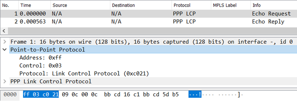
This layer-2 overhead is only 4 bytes. Most networkers don’t often think about PPP encapsulation (I certainly don’t), but this is actually the right answer. Here’s a picture of a packet capture; the address, control, and protocol fields sum to 4 bytes in length and are clearly displayed in the output above. The same is true for all other layer-2 encapsulations supported by the device.
Riding atop this PPP link is a GRE tunnel named Tunnel23. The tunnel overlay supports IPv4, IPv6, and MPLS as evidenced by the output below.
R2#show adjacency Tunnel23
Protocol Interface                 Address
IP       Tunnel23                  point2point(11)
TAG      Tunnel23                  point2point(4)
IPV6     Tunnel23                  point2point(6)
Let’s focus on the MPLS adjacency because that leads to the most fun. While you can use the “detail” keyword as we’ve been doing, let’s try the “encapsulation” keyword instead. This exposes some additional goodies regarding tunnel adjacencies that I personally find useful.
R2#show adjacency Tunnel23 link mpls encapsulation
Protocol Interface                 Address
TAG      Tunnel23                  point2point(4)
  Encap length 24
  4500000000000000FF2F0C79C0A81702
  C0A8170300008847
  Provider: TUNNEL
  Protocol header count in macstring: 2
    HDR 0: ipv4
       dst: static, 192.168.23.3
       src: static, 192.168.23.2
      prot: static, 47
       ToS: static, 0
       ttl: static, 255
        df: static, cleared
      per packet fields: ident tl chksm
    HDR 1: gre
      prot: static, 0x8847
      per packet fields: none
As always, the output includes the encapsulation length followed by a long hexadecimal string. Basic IPv4-based GRE overhead (sans key, checksum, and sequence numbers) is 24 bytes in length, consisting of a 20-byte IPv4 header and a 4-byte GRE header. Both headers, listed as “HDR 0” and “HDR 1”, respectively, are displayed. All of the IPv4 header details are arranged individually in a clean format, which may help with tunnel endpoint troubleshooting. Then, the GRE details are supplied. The protocol ID is 0x8847, indicating that the tunnel will carry MPLS packets. In this example, I’d recommend configuring Tunnel23 with an IP MTU of 1476 bytes, computed by subtracting 24 from 1500 (assuming the PPP link has an IP MTU of 1500 bytes). I’d use the same value for the MPLS MTU as well.
There’s one last wrinkle to discuss on the topic of MPLS, especially as it relates to tunnels and other layers of encapsulation. Let’s assume there’s a large MPLS network behind R3, and some remote device wants to send label-switched traffic through R3 towards R1. R3 would receive MPLS-encapsulated traffic, consult its Label Forwarding Information Base (LFIB), and discover that the egress interface towards R1’s loopback is via Tunnel23. The output below proves that. If you’re not an MPLS expert, don’t worry. Just focus on the encapsulation overhead for now.
R3#show mpls forwarding-table 10.0.0.1 32 detail
Local   Outgoing   Prefix         Bytes Label   Outgoing   Next Hop
Label   Label      or Tunnel Id   Switched      interface
3000    2001       10.0.0.1/32    0             Tu23       point2point
        MAC/Encaps=24/28, MRU=1476, Label Stack{2001}
        4500000000000000FF2F0C79C0A81703C0A8170200008847 007D1000
        No output feature configured
Check out that terrifying string of hexadecimal characters. Look familiar? It should, because the first 24 bytes are identical to what we just reviewed with the GRE adjacency. The last 4-byte chunk represents the MPLS shim header. The first 20 bits of that header (i.e., the first 5 characters) represent the MPLS label value of 0x007D1 (decimal 2001). This value is revealed as the outgoing label and the low-level hexadecimal dump simply confirms it. The last 12 bits are variable per packet and include the S-bit (bottom of stack), experimental bits, and Time To Live (TTL) values; the LFIB uses zeroes as placeholders. Nonetheless, the total encapsulation along this label switched path is actually 28 bytes and could be even more if additional labels are stacked (4 bytes per label). In the screenshot below, I highlight the MPLS label so you can see where it falls in the hexadecimal data dump. It comes right after the 0x8847 at the end of the GRE header and right before the IPv4 payload.
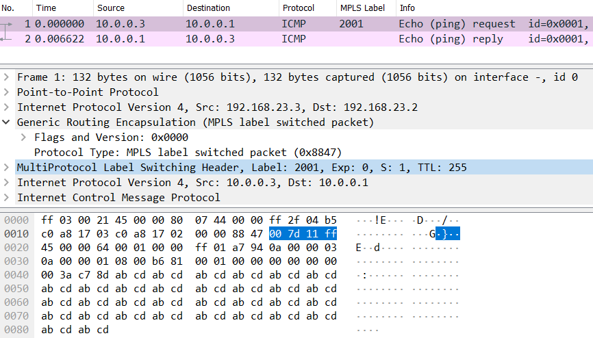
As a bonus, let me teach you a handy Wireshark trick. Notice that each row of hexadecimal data contains 32 characters or 16 bytes. The row counters increment by 16 by adding 0x0010 each time. The MPLS label is the last piece of data before the IP header begins on row 0x0020. That means there are exactly 32 bytes of overhead before the MPLS-encapsulated IP packet: 4 bytes PPP, 24 bytes GRE, and 4 bytes MPLS. In summary, I wrote this blog to add a simple yet powerful tool into your toolbox. I regularly use “show adjacency” and its variants to confirm my assumptions about layer-2 encapsulation lengths. You’ll save yourself and your customers much heartache by getting your MTUs correct the first time! If you enjoyed this blog and my no-nonsense, tech-focused style of training, you’ll love my Cisco Advanced Routing series on Pluralsight.
Reference Configurations:
# R1
version 15.6
!
hostname R1
!
!
no aaa new-model
!
!
!
no ip icmp rate-limit unreachable
!
!
!
no ip domain lookup
ip cef
ipv6 unicast-routing
ipv6 cef
!
mpls label range 1000 1999
!
!
!
!
interface Loopback0
 ip address 10.0.0.1 255.255.255.255
 ipv6 address FC00::1/128
 ospfv3 1 ipv6 area 0
 ospfv3 1 ipv4 area 0
!
interface Ethernet0/0
 description TO R2
 no ip address
!
interface Ethernet0/0.10
 encapsulation dot1Q 10 native
 ip address 10.0.10.1 255.255.255.0
 ipv6 address FE80::1 link-local
 mpls ip
 ospfv3 1 network point-to-point
 ospfv3 1 ipv4 area 0
 ospfv3 1 ipv6 area 0
!
interface Ethernet0/0.11
 encapsulation dot1Q 11
 ip address 10.0.11.1 255.255.255.0
 ipv6 address FE80::1 link-local
 mpls ip
 ospfv3 1 network point-to-point
 ospfv3 1 ipv4 area 0
 ospfv3 1 ipv6 area 0
!
interface Ethernet0/0.12
 encapsulation dot1Q 12 second-dot1q 13
 ip address 10.0.12.1 255.255.255.0
 ipv6 address FE80::1 link-local
 mpls ip
 ospfv3 1 network point-to-point
 ospfv3 1 ipv4 area 0
 ospfv3 1 ipv6 area 0
!
interface Ethernet0/1
 no ip address
 shutdown
!
interface Ethernet0/2
 no ip address
 shutdown
!
interface Ethernet0/3
 no ip address
 shutdown
!
router ospfv3 1
 !
 address-family ipv4 unicast
 exit-address-family
 !
 address-family ipv6 unicast
 exit-address-family
!
!
mpls ldp router-id Loopback0
!
end
# R2
version 15.6
!
hostname R2
!!
no aaa new-model
!
!
!
!
!
no ip icmp rate-limit unreachable
!
!
!
!
no ip domain lookup
ip cef
ipv6 unicast-routing
ipv6 cef
!
mpls label range 2000 2999
!
!
!
!
interface Loopback0
 ip address 10.0.0.2 255.255.255.255
 ipv6 address FC00::2/128
 ospfv3 1 ipv6 area 0
 ospfv3 1 ipv4 area 0
!
interface Tunnel23
 ip address 10.2.3.2 255.255.255.0
 ipv6 address FE80::2 link-local
 mpls ip
 ospfv3 1 ipv6 area 0
 ospfv3 1 ipv4 area 0
 tunnel source 192.168.23.2
 tunnel destination 192.168.23.3
!
interface Ethernet0/0
 description TO R1
 no ip address
!
interface Ethernet0/0.10
 encapsulation dot1Q 10 native
 ip address 10.0.10.2 255.255.255.0
 ipv6 address FE80::2 link-local
 mpls ip
 ospfv3 1 network point-to-point
 ospfv3 1 ipv4 area 0
 ospfv3 1 ipv6 area 0
!
interface Ethernet0/0.11
 encapsulation dot1Q 11
 ip address 10.0.11.2 255.255.255.0
 ipv6 address FE80::2 link-local
 mpls ip
 ospfv3 1 network point-to-point
 ospfv3 1 ipv4 area 0
 ospfv3 1 ipv6 area 0
!
interface Ethernet0/0.12
 encapsulation dot1Q 12 second-dot1q 13
 ip address 10.0.12.2 255.255.255.0
 ipv6 address FE80::2 link-local
 mpls ip
 ospfv3 1 network point-to-point
 ospfv3 1 ipv4 area 0
 ospfv3 1 ipv6 area 0
!
interface Ethernet0/1
 no ip address
 shutdown
!
interface Ethernet0/2
 no ip address
 shutdown
!
interface Ethernet0/3
 no ip address
 shutdown
!
interface Serial1/0
 ip address 192.168.23.2 255.255.255.0
 encapsulation ppp
 serial restart-delay 0
!
interface Serial1/1
 no ip address
 shutdown
 serial restart-delay 0
!
interface Serial1/2
 no ip address
 shutdown
 serial restart-delay 0
!
interface Serial1/3
 no ip address
 shutdown
 serial restart-delay 0
!
router ospfv3 1
 !
 address-family ipv4 unicast
 exit-address-family
 !
 address-family ipv6 unicast
 exit-address-family
!
mpls ldp router-id Loopback0
!
end
# R3
hostname R3
!
no aaa new-model
!
!
!
!
no ip icmp rate-limit unreachable
!
!
!
no ip domain lookup
ip cef
ipv6 unicast-routing
ipv6 cef
!
mpls label range 3000 3999
!
!
!
!
interface Loopback0
 ip address 10.0.0.3 255.255.255.255
 ipv6 address FC00::3/128
 ospfv3 1 ipv6 area 0
 ospfv3 1 ipv4 area 0
!
interface Tunnel23
 ip address 10.2.3.3 255.255.255.0
 ipv6 address FE80::3 link-local
 mpls ip
 ospfv3 1 ipv6 area 0
 ospfv3 1 ipv4 area 0
 tunnel source 192.168.23.3
 tunnel destination 192.168.23.2
!
interface Ethernet0/0
 no ip address
 shutdown
!
interface Ethernet0/1
 no ip address
 shutdown
!
interface Ethernet0/2
 no ip address
 shutdown
!
interface Ethernet0/3
 no ip address
 shutdown
!
interface Serial1/0
 ip address 192.168.23.3 255.255.255.0
 encapsulation ppp
 serial restart-delay 0
!
interface Serial1/1
 no ip address
 shutdown
 serial restart-delay 0
!
interface Serial1/2
 no ip address
 shutdown
 serial restart-delay 0
!
interface Serial1/3
 no ip address
 shutdown
 serial restart-delay 0
!
router ospfv3 1
 !
 address-family ipv4 unicast
 exit-address-family
 !
 address-family ipv6 unicast
 exit-address-family
!
mpls ldp router-id Loopback0
!
end